Kia Picanto (JA): Clutch System / Clutch Release Fork and Clutch Release Bearing
Components and components location
| Components |
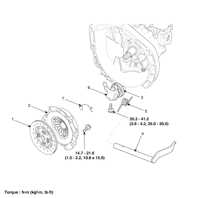
| 1. Clutch disc assembly 2. Clutch cover assembly 3. Clutch release bearing 4. Clutch release lever assembly | 5. Return spring 6. Clutch release fork 7. Return clip |
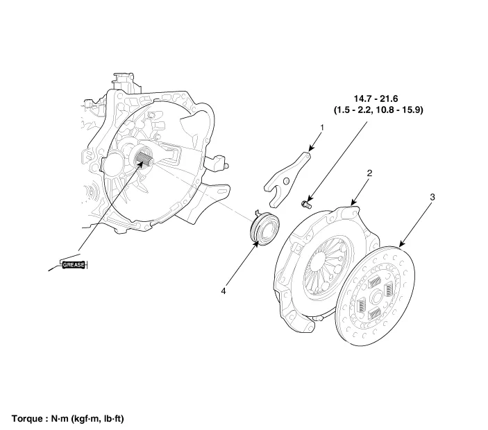
| 1. Clutch release fork 2. Clutch cover assembly | 3. Clutch disk assembly 4. Clutch release bearing |
Repair procedures
| Removal |
| 1. | Remove the transaxle assembly.
G 1.0 MPI KAPPA (Refer to Manual Transaxle System - "Manual Transaxle")
G 1.2 MPI KAPPA (Refer to Manual Transaxle System - "Manual Transaxle")
F 1.0 KAPPA FFV (Refer to Manual Transaxle System - "Manual Transaxle")
|
| 2. | Remove the reamer bolt.
|

| 3. | Remove the return clip (A) from the release bearing and then remove the release fork and release bearing.
|

| 1. | Remove the transaxle assembly.
G 1.0 T-GDI KAPPA (Refer to Manual Transaxle System - "Manual Transaxle")
|
| 2. | Remove the clutch release bearing (A).
|

| 3. | Pull the clip (A).
|

| 4. | Remove the clutch release fork (A).
|

| 5. | Remove the boot (A).
|

| Installation |
| 1. | Apply multi purpose grease to release fork assembly.
|

| 2. | Apply multi purpose grease into the groove of the release bearing.
|

| 3. | Install the release bearing and release fork to clutch housing.
|

| 4. | Install the reamer bolt.
|
| 5. | Apply multi purpose grease to on contact surface of lever (A).
|

| 6. |
Clean the surfaces of the flywheel and pressure plate throughly with
fine sandpaper or crocus cloth, and make certain that all oil or grease
has been removed. |
| 7. | Apply a small amount of multi purpose grease to the input shaft splines (A).
|

| 8. | Clean
the surfaces of the flywheel and pressure plate thoroughly with fine
sandpaper or crocus cloth, and make certain that all oil or grease has
been removed. |
| 9. | Install the transaxle assembly.
G 1.0 MPI KAPPA (Refer to Manual Transaxle System - "Manual Transaxle")
G 1.2 MPI KAPPA (Refer to Manual Transaxle System - "Manual Transaxle")
F 1.0 KAPPA FFV (Refer to Manual Transaxle System - "Manual Transaxle")
|
| 1. | Install the boot (A).
|
| 2. | Install the clip to the clutch release fork. |
| 3. | Apply to grease in location A, B and C.
|

| 4. | Apply the grease to the hole surface of the clutch release bearing all around.
|

| 5. | Install the clutch release fork (B), clutch release bearing (A).
|

| 6. | Install the transaxle assembly.
G 1.0 T-GDI KAPPA (Refer to Manual Transaxle System - "Manual Transaxle")
|
Repair procedures Removal [Kappa 1.0 T-GDI] 1.Remove the engine room under cover. G 1.0 T-GDI KAPPA (Refer to Engine Mechanical System - "Engine Room Under Cover") 2.
Specifications Specifications Transaxle model M5CF1-1 Engine type Gasoline 1.0 T-GDI Manual transalxe oil Capacity 1.
Other information:
Kia Picanto (JA) 2017-2026 Service & Repair Manual: Power Door Lock Switch
Repair procedures Inspection 1.Check for continuity between the terminals. If there is an abnormality, replace the switch. Removal • When removing with a flat-tip screwdriver or remover, wrap protective tape around the tools to prevent damage to components.
Kia Picanto (JA) 2017-2026 Service & Repair Manual: Windshield Wiper-Washer Switch
Repair procedures Removal 1.Disconnect the negative (-) battery terminal. 2.Remove the steering column upper and lower shrouds after loosening the screws. (Refer to Body - "Steering Column Shroud Panal") 3.Disconnect the wiper switch / washer switch connector (A).
Categories
- Manuals Home
- Kia Picanto Owners Manual
- Kia Picanto Service Manual
- Timing Chain
- Fuel Delivery System
- Battery
- New on site
- Most important about car
