Kia Picanto (JA): Engine Mechanical System / Cylinder Head Assembly
Components and components location
| Components |
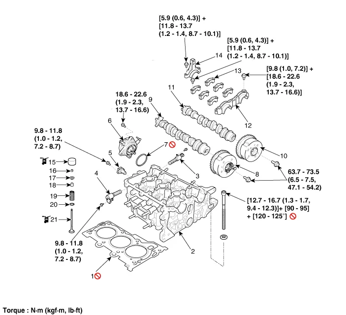
| 1. Cylinder head gasket 2. Cylinder head 3. Intake oil control valve (OCV) 4. Exhaust oil control valve (OCV) 5. Exhaust camshaft position sensor (CMPS) 6. Vacuum pump 7. Vacuum pump O-ring | 8. Exhaust CVVT assembly 9. Exhaust camshaft 10. Intake CVVT assembly 11. Intake camshaft 12. Camshaft front bearing cap 13. Camshaft middle bearing cap 14. Camshaft rear bearing cap | 15. Mechanical lash adjuster (MLA) 16. Retainer lock 17. Retainer 18. Valve stem seal 19. Valve spring 20. Valve spring seat 21. Valve |
Repair procedures
| Valve Clearance Inspection And Adjustment |
Inspect
and adjust the valve clearance when the engine is cold (Engine coolant
temperature : 20°C (68°F)) and cylinder head is installed on the
cylinder block. |

| 1. | Remove the cylinder head cover.
(Refer to Cylinder Head Assembly - “Cylinder Head Cover”)
|
| 2. | Set No.1 cylinder to TDC/compression.
|


| 3. | Inspect the valve clearance.
|


| 4. | Adjust the intake and exhaust valve clearance.
|

Repair procedures Disassembly • Use fender covers to avoid damaging painted surfaces.• To avoid damaging the cylinder head, wait until the engine coolant temperature drops below normal temperature (20°C [68°F]) before removing it.
Components and components location Components 1. Oil filler cap 2. Cylinder head cover 3. Cylinder head cover gasket Repair procedures Removal • Use fender covers to avoid damaging painted surfaces.
Other information:
Kia Picanto (JA) 2017-2026 Service & Repair Manual: Back View Camera System
Components and components location Component Location 1. Back view camera 2. AVN head unit 3. steering angle sensor Description and operation Description 1. To display back of the vehicle to assist the driver, it receives vehicle rearside image signal from the rearview camera and displays it on AVN head unit monitor
Kia Picanto (JA) 2017-2026 Service & Repair Manual: Button Engine Start System
Components and components location Component Location 1. Body control module (BCM) 2. Smart key unit (SMK) 3. Interior antenna 1 4. Interior antenna 2 5. FOB key 6. Start Stop Button (SSB) 7. Door handle & door antenna 8. Bumper antenna 9.
Categories
- Manuals Home
- Kia Picanto Owners Manual
- Kia Picanto Service Manual
- Features of your vehicle
- Body Electrical System
- Charging System
- New on site
- Most important about car
