Kia Picanto (JA): Floor Console / Floor Console Assembly
Components and components location
| Component Location |
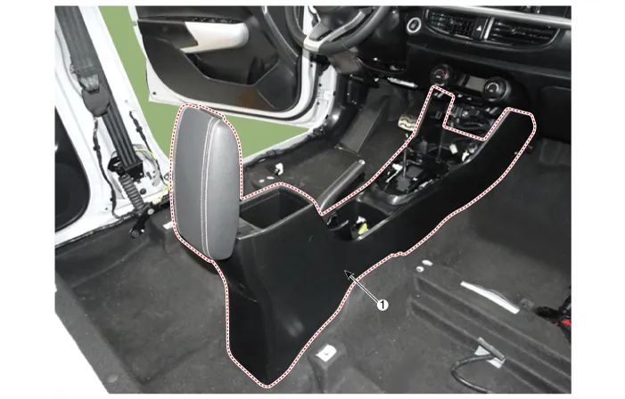
| 1. Floor console assembly |
Repair procedures
| Replacement |
Put on gloves to protect your hands. |

|

| 1. | To remove the gear knob & gear boots (A) pull both of it up.
|

| 2. | Separate the console upper cover (A) by using a remover.
|

| 3. | Remove the indicator cover, after disconnecting the connectors (A).
|

| 4. | Separate the console front tray (A).
|

| 5. | Remove the console front tray, after disconnecting the connectors (A).
|

| 6. | Remove the parking brake cover (A).
|

| 7. | Remove the console armrest mat (A).
|

| 8. | Remove the console complete (A).
|

| 9. | Install in the reverse order of removal.
|
Components and components location Components [M/T] 1. Floor console assembly 2. Rear console tray mat 3. Parking brake cover 4. Floor console front bezel assembly 5.
Components and components location Component Location 1. Rear console cover Repair procedures Replacement Put on gloves to protect your hands.
Other information:
Kia Picanto (JA) 2017-2026 Service & Repair Manual: Mic
Repair procedures Inspection 1.Disconnect the negative (-) battery terminal. 2.Remove the roof trim assembly. (Refer to Body - "Roof Trim Assembly") 3.Remove the hands free mic (A) after loosening the mounting screws. 4.Check tshe continuity of between terminals.
Kia Picanto (JA) 2017-2026 Service & Repair Manual: Evaporator Core
Repair procedures Replacement 1.Disconnect the negative (-) battery terminal. 2.Remove the heater unit. (Refer to Heater - "Heater Unit") 3.Remove the Evaporator temperature sensor. (Refer to Air Conditioning System - "Evaporator Temperature Sensor") 4.
Categories
- Manuals Home
- Kia Picanto Owners Manual
- Kia Picanto Service Manual
- Suspension System
- Cylinder Head
- Clutch Cable
- New on site
- Most important about car
