Kia Picanto (JA): Body Electrical System / Fuses And Relays
Components and components location
| Component Location |
| [Engine Room] |
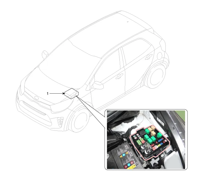
| 1. Engine room relay block |
| [Interior Relay] |
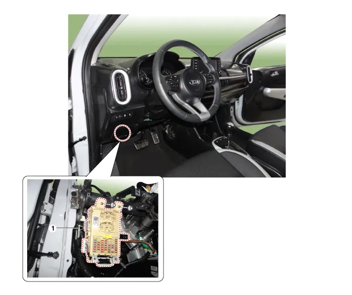
| 1. Interior junction block |
Components and components location Component Repair procedures Removal 1. Disconnect the negative (-) battery terminal. 2. Using a screwdriver or remover, separate the map lamp lens (A) from the map lamp.
Components and components location Component Location E/R Junction Box Circuit (E/R Junction Block) E/R Junction Box Circuit (E/R Junction Block) Repair procedures Inspection 1.
Other information:
Kia Picanto (JA) 2017-2026 Service & Repair Manual: Ignition Switch Assembly
Repair procedures Inspection 1.Disconnect the key warning switch connector (A) and ignition switch connector (B) from the steering column. 2.Check for continuity between the terminals. 3.If continuity is not specified, replace the switch.
Kia Picanto (JA) 2017-2026 Service & Repair Manual: Front Washer Motor
Repair procedures Inspection Front Washer Motor 1.With the washer motor connected to the reservoir tank, fill the reservoir tank with water. • Before filling the reservoir tank with water, check the filter for foreign material or contamination.
Categories
- Manuals Home
- Kia Picanto Owners Manual
- Kia Picanto Service Manual
- Fuel Delivery System
- Clutch Cable
- Coolant
- New on site
- Most important about car
