Kia Picanto (JA): Brake System / Brake Pedal
Components and components location
| Components |
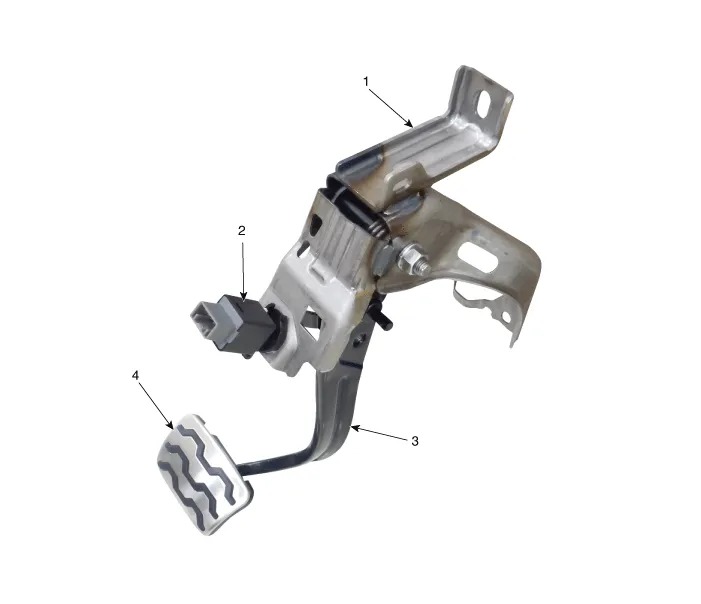
| 1. Brake member assembly 2. Stop lamp switch | 3. Brake Pedal Arm Assembly 4. Brake pedal Pad |
Repair procedures
| Removal |
| 1. | Switch "OFF" ignition and disconnect the negative (-) battery terminal. |
| 2. | Remove the crash pad lower panel.
(Refer to Body - "Crash Pad Lower Panel")
|
| 3. | Remove the steering column.
(Refer to Steering System - "Steering Column and Shaft")
|
| 4. | Remove the snap pin (A) and clevis pin (B).
|

| 5. | Remove the cable pin from the brake pedal.
|

| 6. | Disconnect the clip from the brake pedal .
|

| 7. | Disconnect the stop lamp switch connector (A).
|

| 8. | Remove the brake pedal mounting nuts (A).
|


| Inspection |
| 1. | Check the bushing for wear. |
| 2. | Check the brake pedal for bending or twisting. |
| 3. | Check the brake pedal return spring for damage. |
| Installation |
| 1. | Install in the reverse order of removal |
Components and components location Components Repair procedures Removal 1.Remove the brake fluid level sensor connector. 2.Remove the brake fluid from the master cylinder reservoir with a syringe.
Components and components location Components 1. Guid bolt 2. Caliper body 3. Caliper member 4. Pad liner 5. Brake pad assembly [OUT] 6. Brake pad assembly [IN] 7.
Other information:
Kia Picanto (JA) 2017-2026 Service & Repair Manual: Immobilizer Control Unit
Repair procedures Removal 1.Disconnect the negative (-) battery terminal. 2.Remove the main crash pad assembly. (Refer to Body - "Main Crash Pad Assembly") 3.Disconnect the connector of the immobilizer unit and then remove the immobilizer unit (A) after loosening a bolt.
Kia Picanto (JA) 2017-2026 Service & Repair Manual: Rear Wiper/Washer
C
Categories
- Manuals Home
- Kia Picanto Owners Manual
- Kia Picanto Service Manual
- Cylinder Head
- Suspension System
- Battery
- New on site
- Most important about car

Copyright © 2026 www.kpicanto.com - 0.0165