
Kia Picanto (JA): Your vehicle at a glance / Engine compartment
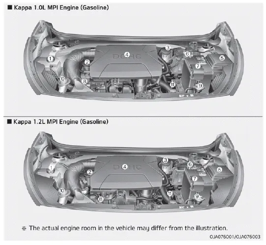
1. Engine coolant reservoir
2. Engine oil filler cap
3. Brake / clutch fluid reservoir
4. Air cleaner
5. Fuse box
6. Negative battery terminal
7. Positive battery terminal
8. Engine oil dipstick
9. Radiator cap
10. Windshield washer fluid reservoir
11. Automatic transaxle fluid dipstick
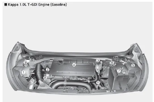
1. Engine coolant reservoir
2. Engine oil filler cap
3. Brake / clutch fluid reservoir
4. Air cleaner
5. Fuse box
6. Negative battery terminal
7. Positive battery terminal
8. Engine oil dipstick
9. Radiator cap
10. Windshield washer fluid reservoir
11. Automatic transaxle fluid dipstick
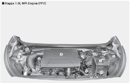
1. Engine coolant reservoir
2. Engine oil filler cap
3. Brake / clutch fluid reservoir
4. Air cleaner
5. Fuse box
6. Negative battery terminal
7. Positive battery terminal
8. Engine oil dipstick
9. Radiator cap
10. Windshield washer fluid reservoir
11. Automatic transaxle fluid dipstick
12. Gasoline reservoir
1. Instrument cluster 2. Horn 3. Driver’s front air bag 4. Light control/Turn signals 5. Wiper/Washer 6. Ignition switch ENGINE START/STOP button 7.
Other information:
Kia Picanto (JA) 2017-2026 Service & Repair Manual: Rear Glass Defogger
C
Kia Picanto (JA) 2017-2026 Service & Repair Manual: Climate Control Air Filtar
Description and operation Description This has particle filter which eliminates foreign materials and odor. The particle filter includes odor filter as well as conventional dust filter to ensure comfortable interior environment. Repair procedures Replacement 1.
Categories
- Manuals Home
- Kia Picanto Owners Manual
- Kia Picanto Service Manual
- Clutch Cable
- Front Disc Brake
- Body Control Module (BCM)
- New on site
- Most important about car
