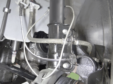
Kia Picanto: Front Suspension System / Front Lower Arm
Repair procedures
| 1. | Remove the front/rear wheel tire (A).
Tightening torque:
107.9 - 127.5 N·m (11.0 - 13.0 kgf·m, 79.6 - 94.0 lb·ft) |
 Be careful not to damage the wheel nuts when removing the front wheel and tire. |
|
| 2. | Remove the lower arm bolt and nut.
Tightening torque:
58.8 - 70.6 N·m (6.0 - 7.2 kgf·m, 43.4 - 52.1 lb·ft) |
 |
| 3. | Remove the front lower arm from the front knuckle using the SST (0K545-A9100). | (1) | After removing bolts from the front knuckle, install and tighten the sub body bolt (A) .
 |
| (2) | Input the sub body (B) between the front knuckle and the sub body bolt. |
| (3) | Tighten the bolt (C) of the sub body to broaden the gap of the front knuckle.
 |
| (4) | Install the safe wire.
 Install a safe wire on the front strut to prevent dropping the SST and injuring technicians. |
|
| (5) | Install the main body (A) between the front strut and the lower arm. |
| (6) | To avoid the main body coming off, install a fixing clamp (B) beside the main body.
 |
| (7) | After installing a body, rotate the handle (A) clockwise util the clamp is fixed on the lower arm.
 |
| (8) | Tighten the main body bolt (A) slowly and remove the lower arm from the front knuckle.
 |
|
| 4. | Remove the lower arm from the sub frame.
Tightening torque:
(A) 117.7 - 137.3 N·m (12.0 - 14.0 kgf·m, 86.8 - 101.3 lb·ft)
(B) 156.9 - 176.5 N·m (16.0 - 18.0 kgf·m, 115.7 - 130.2 lb·ft) |
 |
| 5. | Install in the reverse order of removal. |
| 6. | Check the wheel alignment.
(Refer to Tires/Wheels - "Alignment")
|
Lower arm ball joint
| 1. | Remove the front lower arm.
(Refer to Suspension System - "Front Lower Arm")
|
| 2. | Remove the snap ring (A) from the lower arm ball joint.
 |
| 3. | Using a press, remove the ball joint (A) from the lower arm.
 |
| 4. | Using a press, install the new ball joint.
 |
| 1. | Check the bushing for wear and deterioration. |
| 2. | Check the lower arm for bending or breakage. |
| 3. | Check the lower arm for deformation. |
| 4. | Check all bolts and nuts. |
Components and components location
Components Location
1. Lock nut 2. Insulator dust cap 3. Self lock nut 4. Strut insulator 5. Strut bearing 6. Spring upper seat 7. Spring upper pad 8. Coli ...
Repair procedures
Removal
1.Remove the universal joint bolt (A).
Tightening torque :
32.4 - 37.3 N·m (3.3 - 3.8 kgf·m, 23.9 - 27.5 lb·ft)
•
...
Other information:
All tire pressures (including the spare)
should be checked when the tires are
cold. “Cold Tires” means the vehicle has
not been driven for at least three hours
or driven less than 1.6 km (one mile).
Recommended pressures must be
maintained for the best ride, top vehicle
handling, a ...
Description and operation
Description
An
ignition coil is an induction coil in an engine's ignition system which
transforms the battery's low voltage to the high voltage needed to
create an electric spark in the spark plugs to ignite the fuel. Coils
have an internal resistor while othe ...
 Front Strut Assembly
 Front Stabilizer Bar


